This page explains the criteria that were used to test avalanche transceivers for BeaconReviews.com.
Throughout all of my testing, I strive to keep the tests as scientifically accurate and unbiased as possible and to avoid subjectivity. I don't have an incentive to do otherwise.
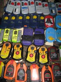
Over the past 14 years, I have measured the reception range of avalanche transceivers 421 times in 15 different sessions. These tests involved 167 different transceivers. All of these included measuring the range with the receiving transceiver's body held inline with the transmitting beacon's antenna. In 172 of those tests, I also measured the reception range when the receiving transceiver's body was perpendicular to the transmitter's antenna (for a total of 593 measurements).
I have strived to keep the tests as objective as possible by replacing all batteries at the start of the testing, testing the ranges of previously tested transceivers to adjust for daily variations (e.g., due to the transmitter, background noise, atmospheric conditions, etc), testing a large sampling of transceivers during each session (typically 15+ transceivers, but sometimes 40+), including multiple people in the testing (a minimum of three, but typically five+), having a dedicated scribe, using written protocols that are read to all of the testers before the testing began (e.g., cell phones off, how to determine when a transceiver has received signal, etc), retesting any results that were unusual, keeping track of which transceiver was transmitting, recording the ambient air temperature, etc, etc.
Preparation
Distances

Learn how to test your avalanche transceiver.
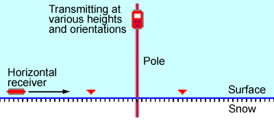
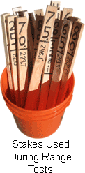
To test if a transceiver can ignore spikes, the transmitting beacon was placed two and three meters above the ground on a non-metallic pole (this is easier than digging a three-meter hole). Tape measures were run from the base of the pole in opposite directions on the ground. I do not use BCA Tracker (because the antennas are not inline with its housing) or Ortovox transceivers (because they use orientation-based transmitting) as the transmitting beacon. The receiving beacon is then moved very slowly along the ground, in a straight line, to search for the strongest signal(s).

The spike testing was performed on numerous sessions, using different transmitting beacons, at different "depths."
It is very challenging to objectively test a transceiver's ability to mark (aka ignore) a transceiver due to the numerous variables (e.g., signal overlap, the distance between the transceivers, antenna orientation, etc). In most cases I reserve judgment on a transceiver's ability to mark a transceiver unless I see repeated problems. I do comment on how intuitive it is to mark a transceiver.
My typical multiple burial test involved placing two transceivers approximately five meters apart. The searching transceiver was then changed to search mode (sometimes within the receiver's range where it would immediately pick up a single and sometimes from a distance where no signal was received). This process was repeated using two transmitting beacons of the same brand (without signal overlap), using two transmitting beacons with different cadences (periodic signal overlap), and using two beacons using the DSP's Smart Transmitter (different brands, without signal overlap).
The "suppress" functions were used to see if the searching beacon would consistently suppress the victim's beacon and if the searching beacon would direct the searcher to the next victim.
Most of my multiple burial testing has been limited to two transmitters, although in the fall of 2010 I did numerous tests of the Ortovox 3+ with three transmitters.
(Read about multiple burials and transceiver marking on AvyRescue.com.)

 In almost every case, the dimensions listed in the comparison table are the actual sizes as measured with calipers. Small protrusions that are less than ~5% (such as the triangular Search switch on this ARVA Link) were not included.
The volume of the transceivers was calculated by multiplying the length, width, and depth. The volumes ignore a transceiver's nooks-and-crannies.
The weights listed in the comparison table are the actual weights including the harness and batteries. If you choose to "display more information" in the comparison table, the weight with batteries but without the harness is displayed.
 Session #1 took place on January 15, 2004. The air temperature was approximately 18 F (-8 C). The ground was covered with approximately 6" of snow. The transmitting transceiver was an Ortovox M2 placed on top of the snow. Five beacons were tested.
Session #2 took place on January 17, 2006. The outside temperature was approximately 25 F (-4 C). The ground was covered with approximately 3 meters of snow. The transmitting transceiver was a Pieps DSP placed on top of snow. Seven beacons were tested.
Session #3 took place on January 18, 2006. The conditions were similar to Session #2. Four beacons were tested.
Session #4 took place on February 27, 2006. The outside temperature was approximately 50 F (10 C). Three beacons were tested.
Session #5 took place on October 24, 2006. The outside temperature was approximately 65 F (18 C). The test was done in a city with some background noise (a faint music radio could be heard). The surface was a lawn. The transmitting transceiver was an ARVA Evolution+. The six transceivers tested had an average increase in range of 50%! Whether the increase was due to the transmitting beacon (an ARVA Evolution+), the temperature or other environmental conditions, these values were not averaged into the test results. Six beacons were tested.
Session #6 took place on November 12, 2006 in a remote area in the mountains. The air temperature was approximately 26 F. The ground was covered with approximately two feet of snow. The transmitting beacon was a Tracker DTS placed on top of the snow. Ten trained rescuers tested 53 transceivers at this mother-of-all-tests.
Session #7 took place on December 5, 2006. During range testing, the outside temperature was between 23 F and 26 F. The ground was frozen dirt with approximately 2 inches of snow. For performance and spike testing, the temperature was approximately 33 F and the ground was covered with two feet of snow. The transmitting beacon was an Ortovox M2. Nine beacons were tested.
Session #8 took place on December 27, 2007. The outside temperature was approximately 22 F. The ground was covered with approximately 12 inches of snow. The transmitting beacon was a Tracker DTS that was inline (so the transmitting antenna was at an angle) with the receiving beacons. Eight beacons were tested.
Session #9 also took place on December 27, 2007, but at a different location. The outside temperature was approximately 15 F. The ground was covered with approximately three feet of snow. The transmitting beacon was a Pieps DSP with v5.0 software. Nine beacons were tested.
Session #10 took place on November 19, 2008. The outside temperature was approximately 24 F. The ground was covered with approximately two feet of snow. Ten transceivers were tested using two different transmitters.
Session #11 also took place on November 19, 2008. This test measured the ability of nine transceivers to transmit a signal. The outside temperature was approximately 29 F. The ground was covered with two feet of snow. The receiving beacons were a Pieps DSP and an ARVA Advanced.
Session #12 took place on January 24, 2010. The outside temperature was approximately 14 F. The ground was covered with approximately four feet of snow. Fifteen transceivers were tested using two different transmitters.
Session #13 took place on January 26, 2010. This session included exhaustive testing of spike handling, at both one and two meters, using 11 different avalanche transceiver models.
Session #14 took place on October 15, 2010. This outside temperature was approximately 70 F (warm). The ground was dry grass in a large city park. There was minimal background noise and no visible power lines. Eight beacons were tested (include three Ortovox 3+ transceivers). An Ortovox multiple transmitting test station was used to simulate multiple burials.
Session #15 took place on December 14, 2012 in a large city park. We could hear a faint radio station when using an analog transceiver. The range of 34 transceivers (20 different models) were tested.
Session #16 took place on October 31, 2014 in a large city park on dry grass. The temperature was approximately 70 F (warm). There was minimal background noise, but there were power lines in the distance. We tested 18 beacons two times each (using a different transmitting beacon). We also tested all 18 beacons in perpendicular-antenna orientation.
Session #16 took place on December 3, 2016 in the Utah mountains. Seven people tested the ranges of 43 avalanche transceivers (both inline and perpendicular, twice).
Session #17 took place on December 31, 2018 in the Utah mountains. Seven members of the Salt Lake County Search and Rescue assisted me. We tested the ranges of 29 avalanche transceivers in inline, perpendicular, and vertical orientations (93 measurements total).
I have done a lot of testing beyond the tests shown above, but those are the larger-scale, formal tests.